  • Products
  • Evaluate our Software
  • Downloads
  • Free Utilities
  • Purchase
  • Support
  • About Us
  • Blog
  • Forum
  • Search
    • Contact Us
    • Forum
    • Knowledge Base
    • Web Shop
    • Newsletter
    • RSS
  •   Jobs
  •   Videos
  •   Blog
  •   Sustainability
  • J-Link debug probes
  • 10-Pin Needle Adapter
  • Technology
  • Accessories
  • Tools
  • Models

10-Pin Needle Adapter

The 10-Pin Needle Adapter connects a J-Link or Flasher to a PCB which does not come with a mating connector or programming header.

Buy now
Compare J-Link adapters
Documentation
SEGGER Debug & Trace Probes
  1. 1.Overview
    1. 1.1.Key Features
  2. 2.Pinout
  3. 3.Footprint
    1. 3.1.Layout Problems to Avoid
  4. 4.Schematics

Overview

The 10-Pin Needle Adapter has been designed to connect J-Link or Flasher to a PCB which does not come with a mating connector or programming header. The designed pattern with 3 locating pins ensures that the adapter can only be connected in one way. The needle adapter allows manufacturers to save costs and space on their PCBs since there is no need to provide the PCB with additional connectors. It adapts from the standard 20-pin 0.1'' connector to a 10-pin needle connector.

Key Features

  • No additional connector required on your PCB
  • Very small footprint
  • High reliability spring pins for secure connections
  • Designed with 3 locating pins, so the adapter cannot be connected the wrong way
  • No external power supply required! The 10-Pin Needle Adapter comes with the option to power the target hardware via J-Link or Flasher
10-Pin Needle Adapter with cable

Pinout

As you can see on the image below, the three locating pins ensure that the adapter cannot be connected to the PCB the wrong way. Moreover, the two "legs" on each side of the connector guarantee a stable and secure contact between pins and the PCB.

J-Link_Needle_Adapter_plugged
10-Pin Needle Adapter Pinout
J-Link_Needle_Adapter_Connector_pins

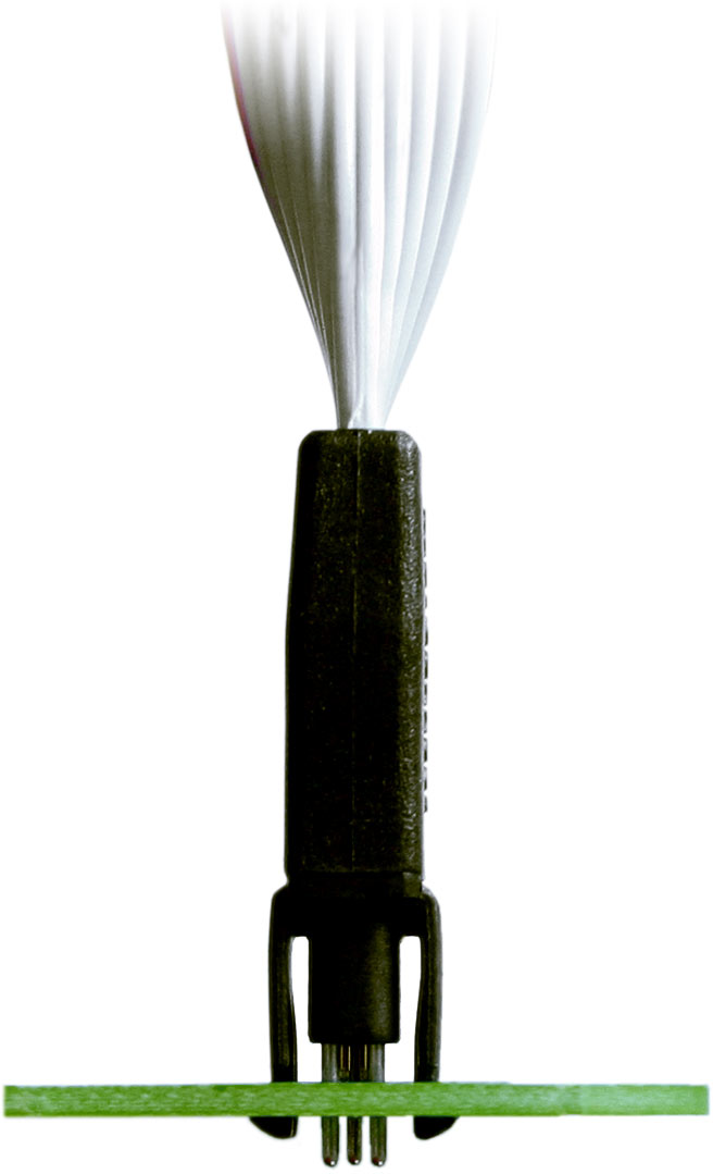
Three locating pins ensurethat the adapter cannot be connected the wrong way:

10-pin-needle-adapter-removing-legs

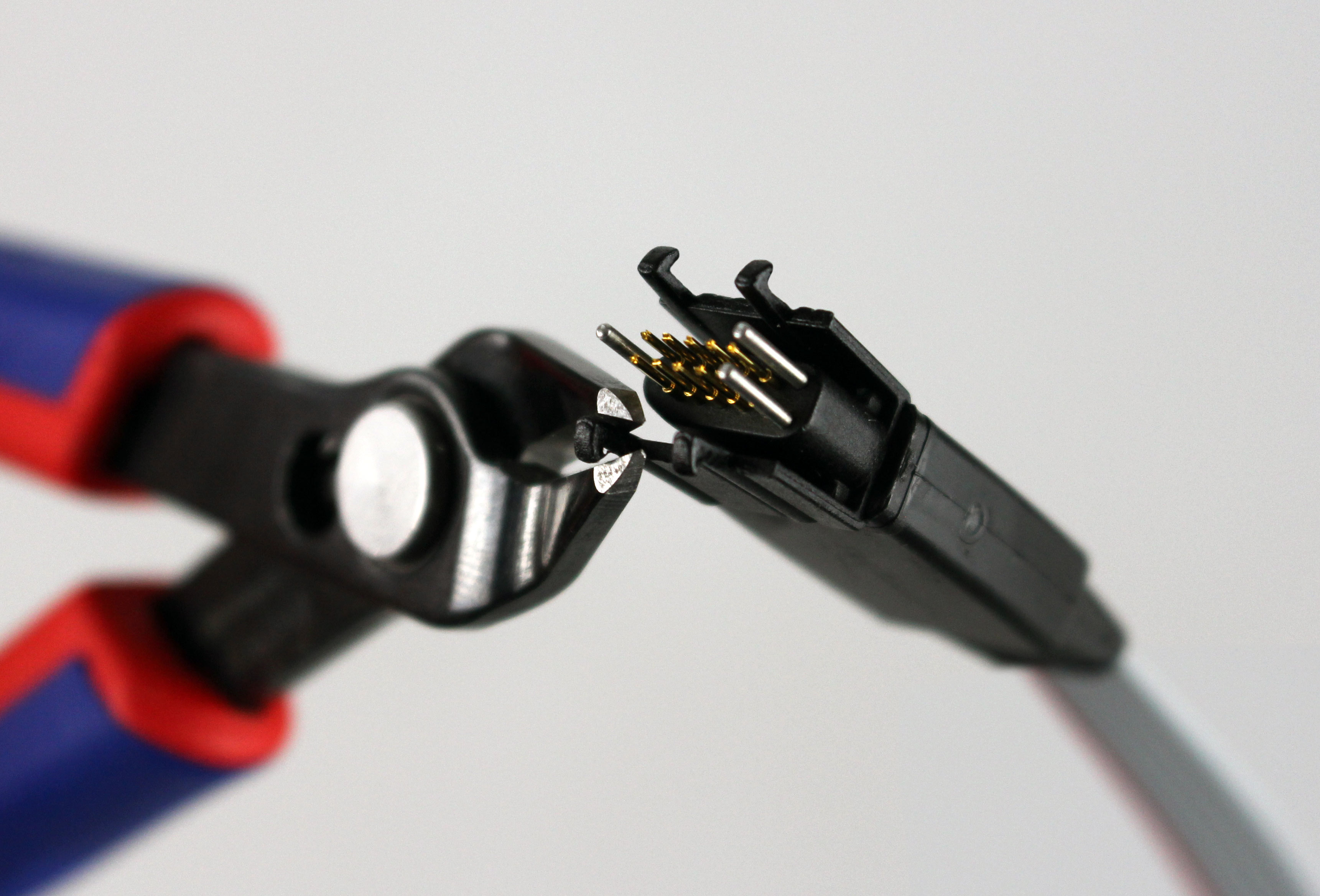
In case of space problems, the two "legs" on each side can easily be cut off as shown in the image below:

Footprint

10-Pin Needle Adapter Footprint
10-Pin Needle Adapter PCB

Layout Problems to Avoid

Please be sure to avoid the situations illustrated below to ensure the 10-Pin Needle Adapter functions properly. The PDF version of the datasheet can be downloaded here. In addition to the footprint and hints to avoid layout problems, this PDF includes detailed information about the cable, plug, and connector of the 10-Pin Needle Adapter.

J-Link_Needle_Adapter_Avoid

Schematics

The following picture shows the connections from the 20-pin standard JTAG connector to the 10-pin, 0.05 inch needle pattern:

10-Pin Needle Adapter Schematics

Headquarters

SEGGER Microcontroller GmbH

Ecolab-Allee 5
40789 Monheim am Rhein, Germany
info@segger.com
Tel.: +49-2173-99312-0
Fax: +49-2173-99312-28

Locations

USA: SEGGER Microcontroller Systems LLC

Boston area
101 Suffolk Lane
Gardner, MA 01440, USA
us-east@segger.com
Tel.: +1-978-874-0299
Fax: +1-978-874-0599

Silicon Valley
Milpitas, CA 95035, USA
us-west@segger.com
Tel.: +1-408-767-4068

China: SEGGER Microcontroller China Co., Ltd.

Room 218, Block A, Dahongqiaoguoji
No. 133 Xiulian Road
Minhang District, Shanghai 201199, China
china@segger.com
Tel.: +86-133-619-907-60

ISO 9001 certified

ISO 9001

30+ years of experience

First-class embedded software tools since 1992
  • Imprint
  • Disclaimer
  • Privacy Policy
© 2025 SEGGER - All rights reserved.