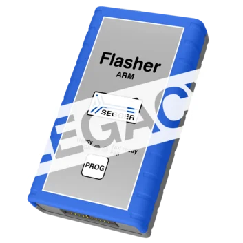
Flasher ARM
The flash programmer for Arm-based microcontrollers
Overview
Flasher ARM is a legacy device with firmware that is still actively maintained. As a current alternative, we recommend Flasher Pro.
Flasher ARM programs non-volatile memories of Arm-based microcontrollers, systems on a chip (SoCs), and external flashes (such as (Q)SPI) that are directly connected to a microcontroller. It supports a wide range of Arm cores and offers reliable, efficient programming for both production and development environments.
With support for JTAG, SWD, and a variety of target devices, Flasher ARM ensures fast, automated, and standalone flash programming. This makes it a cost-effective choice for embedded-system developers seeking performance and flexibility as well as modern integration of peripheral devices with extensive development ecosystems.
Key features

Extensive Arm support
Flasher ARM is a cost-effective flash programmer that offers broad device compatibility across embedded applications. It is designed to program virtually any Arm7, Arm9, or Cortex-M, -R, or -A-based microcontroller.

Serial-number assignment
Many modern devices require unique data. Flasher ARM enables programming of variable information, such as serial numbers, Ethernet hardware addresses (MAC), digital signatures, and license keys. These options can be customized for each device by applying patch data to the original firmware.

Flexible control
Flasher ARM is easy to set up and use with SEGGER software tools. Since it can operate as a standalone programmer or be controlled via PC, Flasher ARM offers flexibility for production. In standalone mode, it supports remote control via USB, UART, Ethernet, a TTL trigger, or the push of a button.
Use cases

Production programming for IoT edge devices
In smart manufacturing, Internet-of-Things edge devices (e.g., smart thermostats) built on Arm microcontrollers require fast, reliable firmware deployment. These devices handle real-time sensor data, run RTOS-based applications, and connect via TCP/IP.
Flasher ARM enables secure, high-speed programming directly on the production line, and it integrates easily with automated workflows triggered by digital I/O — making it ideal for integration with robotic or conveyor-based systems. Through standardization on Flasher ARM, manufacturers can ensure consistent firmware deployment during updates or rework, all while leveraging the power and flexibility of Arm-based microcontrollers.

Field updates for health wearables
Wearable tech devices need to be reliable and stay up to date — even after they are deployed. When these devices are powered by Arm microcontrollers, they often include Bluetooth Low Energy tech for communication, USB interfaces, and secure-boot features. With its standalone mode and option to easily trigger updates at the touch of a button, Flasher ARM enables efficient updates — without the need for a PC or internet connection. Using Flasher ARM, teams can update firmware securely and consistently across thousands of units in the field to maintain compliance and functionality in applications powered by Arm-based microcontrollers.
Customer voices
"We bought a few Flasher ARM devices and were able to use them immediately for standalone programming of new boards. Flawless software, flawless hardware, and a really beautiful product. Thanks for making this available."
// Marcus Simons, YiG Engineering, The Netherlands
How Flasher ARM works
Flasher ARM writes firmware to a device's non-volatile memory, verifies the contents, and provides immediate feedback through LEDs, software, or via hardware interfaces such as RS232. It connects to target devices via standard interfaces such as JTAG and SWD and operates in either PC-controlled or standalone mode. In PC-controlled mode, programming is managed directly from a host computer using SEGGER tools like J‑Flash. In standalone mode, Flasher ARM uses preloaded firmware images stored in its internal memory.
Programming can be triggered through the press of a button, a TTL signal, or remotely via USB, UART, RS232, or Ethernet. Unlike UART, RS232 uses different voltage levels and signaling standards. Since the feedback can be read directly over RS232, software is not necessarily required for evaluation.
Tool set


Software
A multi-platform solution, Flasher ARM comes with SEGGER's Flasher Software and Documentation Package for Windows, Linux, and macOS. It provides the tools and resources necessary for configuring, managing, and using Flasher ARM effectively. It also includes flash loaders for all supported devices, including a wide range of target microcontrollers. The list of supported manufacturers, families and devices, and SoCs provides a detailed overview.
The software package can be downloaded free of charge, and it includes future software and firmware updates as well as all new flash loaders for target devices added in the future.
Supported devices
The list of supported manufacturers, families, devices, and SoCs includes tens of thousands of devices in hundreds of device families.
Device not listed? Please don’t hesitate to contact us.
Customer support
Flasher Pro comes with one year (12 months) of Basic Support. Beyond that, SEGGER's Extended Coverage gives users the option to extend the hardware warranty and Basic Support for one additional year (12 months) or two additional years (24 months). These options are only available at the time of purchase, either through the Web Shop or upon request; adding coverage at a later date is not possible.
Product images


Technical specifications
Package content


Accessories

SEGGER's mounting brackets provide a reliable solution for securely fastening Flasher in-circuit programmers. Designed for stability and ease of use, these brackets ensure an organized and professional setup. Mounting brackets are available directly from the SEGGER shop.
Alternatively, SEGGER offers users the option to 3D print mounting brackets themselves. A downloadable ZIP file is provided, containing a STEP file for modifications, an STL file ready for 3D printing, and a PDF file with detailed dimensions.
FAQ
What is the maximum voltage that can be handled by the galvanic isolation of the Ethernet interface?
The Ethernet data lines are galvanically isolated in accordance with IEEE 802.3, tested at 1500 Vrms for one minute.
This isolation applies only to the data lines, not to the Ethernet shield, which has a direct electrical connection to the USB shield and a resistive and capacitive coupling to probe ground (GND).
For effective galvanic isolation, an unshielded twisted pair (UTP) Ethernet cable should be used.
Latest news
Related content
Get in touch with us
Have questions or need assistance? Our Embedded Experts are here to help!
Reach out to us for:
- Licensing quotes
- Technical inquiries
- Project support