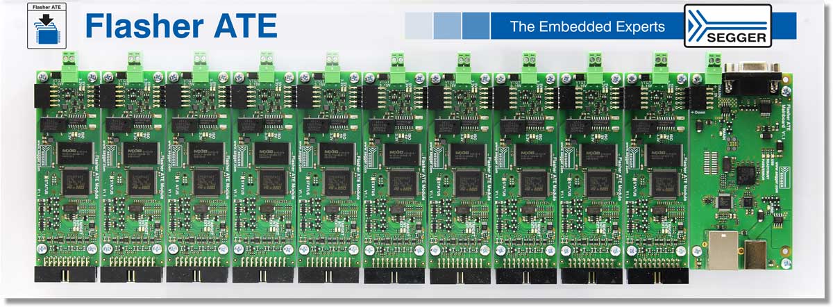
Flasher ATE
The modular gang programmer
The Flasher ATE is a gang programmer specifically designed for direct integration into mass production setups. It is built from a mainboard with up to 10 programming modules.
Please note: Flasher ATE is a legacy product, its successor is Flasher ATE2.

- 1.Supported devices
- 2.Software
- 3.Parallel programming
- 4.Serial number assignment
- 5.Built-in web server
- 5.1.Remote monitoring
- 5.2.Configuration
- 6.Built-in FTP server
- 6.1.Remote file update
- 6.2.Log file
- 7.Media gallery
- 7.1.Product photos
- 7.2.Videos
- 8.Technical specifications
- 9.Assembly dimensions
- 10.Safety
- 11.Package content
- 12.FAQ
- 13.Latest news
Overview
The Flasher ATE is an in-circuit-programmer for high-volume mass production. It is a modular system that uses a communication main board at its heart to distribute commands received from an ATE, ICT or a similar automated production handler system to the attached programming modules. Each individual programming module can be set up with individual configurations and firmware image pairs.
To accommodate the special requirements of high-volume production environments with wide spatial expansions of the ATE workplaces, this gang programmer can be mounted in 19” racks or be connected directly to an ATE. The number of Flasher ATE programming modules per Flasher ATE mainboard can be scaled from 1 to 10 permitting the parallel programming of up to 10 target devices.
The ultra-fast flash algorithms used by the Flasher ATE are the same industry leading and proven algorithms also found in SEGGER’s J-Link debug probes and Flasher programming devices.
Key features
- In-system programmer (ISP)
- High speed programming
- Scalable solution with up to 10 individual channels
- Control interfaces for ATEs and similar production process handlers
- Switchable target power
- Functional isolation of each module
Supported devices
The Flasher ATE is a legacy product for which we do not provide a 'supported devices' overview. If you would like to know if the Flasher ATE supports a specific device, please contact us.
Software
All software is included free of charge. It comes with the flash loaders for all supported devices.
For every Flasher, the Flasher Software and Documentation Package is available:
Parallel programming
The Flasher ATE can gang-up to program up to 10 targets at once. Its ultra-fast programming speed makes it ideally suited for high-volume mass production.
In comparison, the modular in-system programmer Flasher ATE and the Flasher Compact are capable of programming multiple devices in parallel, whether these devices are equal or part of a multi-device system.
Serial number assignment
Many modern devices require some pieces of unique information. Flasher ATE allows the programming of data that differs amongst other otherwise identical units. Typical examples are things like serial numbers, ethernet hardware addresses (MAC), and digital signatures, and license keys that enable/disable product features. All these options can be adapted from device to device by applying patch data to the original firmware.
Built-in web server
The Flasher ATE offers options to check status information remotely and to configure the device.
Remote monitoring
The Flasher ATE comes with SEGGER's built-in web server. It is designed to present important device and current operation data for a quick overview and, additionally, to check the status of the programming units, providing information about:
- Installed firmware version
- Hardware version
- Power consumption
- IP configuration
- Network load
- Current operation and status
- Programming interface in use
This may be important for fast troubleshooting through code verification, for instance, as it is when executing a cyclic redundancy check (CRC) that helps to detect errors during data transmission or storage.

Configuration
If needed, the built-in web server's programmer settings can be checked and adjusted. These could, for example, be parameters like:
- Nickname
- Subnet mask
- Gateway

Built-in FTP server
The Flasher ATE also includes the emFTP server to upload firmware and configuration or download log files.
Remote file update
Using the emFTP server enables easy upload of configuration files and firmware images. By connecting to the emFTP server using an FTP client of choice, files can be transferred between client and Flasher.
Having access to the Flasher configuration via FTP enables configuration of multiple Flashers from a central production control server. This interface can be also used to make the production line part of a CI/CD system to push stable releases into the current production.

Log file
Analyzing the reliability of the production line is an important task, when it comes to increasing the production frequency. This purpose is supported by the built-in FTP server, which lets users check the history of past programming cycles via log file download. Each entry provides the following information:
- Result (success/failure)
- Duration
- Serial number (if programmed)
For failed programming cycles, the log file provides additional information for quick troubleshooting (e.g. failed to open Flasher config file).

Media gallery
Product photos


Videos
Technical specifications
| Specifications | |||||
|---|---|---|---|---|---|
| Power supply | USB powered or via external power supply (5 V), max. 3 A using 10 modules. | ||||
| Ethernet host interface | 10 / 100 MBit | ||||
| USB host interface | USB2.0 (High-Speed), USB Type B | ||||
| RS232 host interface | RS232 9-pin | ||||
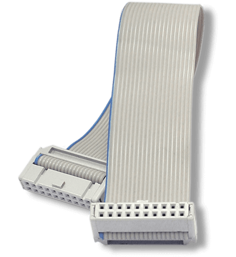
| Target interface | Male 20-pin IDC keyed box header with 0.1" pitch (2.54mm), optional adapters available | ||||
| Max. target cable length | Recommended (delivered): 20 cm (8") Max. 2 m (6.5") allowed but might reduce max. target interface speed. | ||||
| Serial transfer rate between Flasher ATE and target | Max. target interface (JTAG, ...) speed: 15 MHz | ||||
| Supported target voltage | 1.2 - 5 V | ||||
| Current drawn from target voltage sense pin (VTRef) | < 25 µA | ||||
| Target supply voltage | 3 - 15 V (5 V with no additional supply) | ||||
| Target supply current | 100 mA (VCC5V - 5 V) 400 mA (VTGT - 3...15 V) | ||||
| Reset type | Open drain with 100 Ohms series resistor. Can be pulled low or tristated | ||||
| Operating temperature | +5 °C ... +60 °C | ||||
| Storage temperature | -20 °C ... +65 °C | ||||
| Relative humidity (non-condensing) | < 90 % rH | ||||
| Size mainboard (without cables) | 108 mm x 56 mm x 20 mm | ||||
| Weight mainboard (without cables) | 47 g | ||||
| Size programming module (without cables) | 108 mm x 35 mm x 20 mm | ||||
| Weight programming module (without cables) | 24 g | ||||
| Supported OS | Microsoft Windows (x64) | ||||
Safety
This Flasher ATE programming modules provide basic isolation only. Do not use with hazardous voltages without further protection measures to avoid risk of electrical shock and fire.
SEGGER Flasher ATE programming modules provide basic isolation from high voltages. For safety reasons, when dealing with potential hazardous voltages it is mandatory to have a second protection measure in place in case the first insulation barrier fails. This is called double or reinforced isolation. How this double isolation can be achieved depends on the use case or application setup. Also check your local safety directives to make sure all requirements are met.
Package content
Flasher ATE — Programming module

Flasher ATE — Main module


FAQ
Q: How does the access to the individual modules work? How is the programming data transferred? Do I need a Windows DLL?
A: A Windows DLL is not required. The Flasher ATE Programming Modules are set up once - either on the PC or via Ethernet and the corresponding firmware images (one or more) are loaded onto the Flashers. Afterwards, the modules require information on which image should be programmed. Changing data such as serial numbers, MAC addresses etc. can be transferred together with the programming command as "patch data".
Q: Is it possible for the modules to start the programming process automatically when a board has been inserted (measurement of current consumption or periodic attempt of communication setup) or does this have to be done via the interface?
A: Currently programming can only be triggered by the control interfaces RS232, 3-wire-handshake and TELNET.
Q: Is it possible to start the individual modules independently from each other?
A: Yes!