Real Time Transfer (RTT)
SEGGER's Real Time Transfer (RTT) is the proven technology for system monitoring and interactive user I/O in embedded applications. It combines the advantages of SWO and semihosting at very high performance.
Overview
With RTT it is possible to output information from the target microcontroller as well as sending input to the application at a very high speed without affecting the target's real time behavior. SEGGER RTT can be used with any J-Link model and any supported target processor which allows background memory access, which are Cortex-M and RX targets.
RTT supports multiple channels in both directions, up to the host and down to the target, which can be used for different purposes and provide the most possible freedom to the user.
The default implementation uses one channel per direction, which are meant for printable terminal input and output. With the J-Link RTT Viewer this channel can be used for multiple "virtual" terminals, allowing to print to multiple windows (e.g. one for standard output, one for error output, one for debugging output) with just one target buffer. An additional up (to host) channel can for example be used to send profiling or event tracing data.

| Channel | Typical Purpose |
|---|---|
| Up-channel 0 | Terminal output |
| Down-Channel 0 | Keyboard input |
Key features
- Bi-directional communication with the target application
- Very high transfer speed without affecting real time behavior
- Uses debug channel for communication
- No additional hardware or pin on target required
- Supported by any J-Link model
- Supported by ARM Cortex-A/R/M, RISC-V and Renesas RX
- Complete implementation code providing functionality and freedom
How it works
RTT Communication
Communication with the RTT implementation on the target can be done with different applications. The functionality can even be integrated into custom applications using the J-Link SDK.
Using RTT in the target application is made easy. The implementation code is freely available for download and can be integrated into any existing application.
To communicate via RTT any J-Link can be used. The simple way to communicate via the Terminal (Channel 0) is to create a connection to localhost:19021 with a Telnet client or similar, when a connection to J-Link (e.g. via a debug session) is active.
The J-Link Software Package comes with some more advanced applications for different purposes.
Target implementation
For using Real Time Transfer the target code requires instrumentation to collect and prepare the data for communication. The source code of the instrumentation is available at https://github.com/SEGGERMicro/RTT
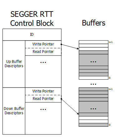
Real Time Transfer uses a SEGGER RTT Control Block structure in the target's memory to manage data reads and writes. The control block contains an ID to make it findable in memory by a connected J-Link and a ring buffer structure for each available channel, describing the channel buffer and its state.
The maximum number of available channels can be configured at compile time and each buffer can be configured and added by the application at run time. Up and down buffers can be handled separately.
Each channel can be configured to be blocking or non-blocking. In blocking mode the application will wait when the buffer is full, until all memory could be written, resulting in a blocked application state but preventing data from getting lost. In non-blocking mode only data which fits into the buffer, or none at all, will be written and the rest will be discarded. This allows running in real time, even when no debugger is connected. The developer does not have to create a special debug version and the code can stay in place in a release application.
Locating the Control Block
When RTT is active on the host computer, either by using RTT directly via an application like RTT Viewer or by connecting via Telnet to an application which is using J-Link, like a debugger, J-Link automatically searches for the SEGGER RTT Control Block in the target's known RAM regions. The RAM regions or the specific address of the Control Block can also be set via the host applications to speed up detection or it the block cannot be found automatically.
Internal structures
The image shows the simplified structure in the target.
There may be any number of "Up Buffer Descriptors" (Target -> Host), as well as any number of "Down Buffer Descriptors" (Host -> Target). Each buffer size can be configured individually. The gray areas in the buffers are the areas that contain valid data. For Up buffers, the Write Pointer is written by the target, the Read Pointer is written by the debug probe (J-Link, Host). When Read and Write Pointers point to the same element, the buffer is empty. This assures there is never a race condition.
Requirements
SEGGER RTT does not need any additional pin or hardware, despite a J-Link connected via the standard debug port to the target. It does not require any configuration of the target or in the debugging environment and can even be used with varying target speeds.
RTT can be used in parallel to a running debug session, without intrusion, as well as without any IDE or debugger at all.
RTT in PC applications
Instead of running an external Telnet client, RTT can also be directly integrated in any PC application, like a debugger, in either of two ways.
The application can either establish a socket connection to the RTT Telnet Server (listening on localhost:19021) or use the J-Link RTT API which is part of the J-Link SDK, to directly configure RTT and get / send data.
Using colors for text output
All data read via RTT is flushed like read from the target without any modification.
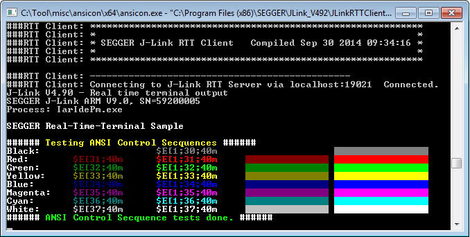
This allows processing of ANSI control sequences by the application which prints the RTT data to display data in bold or change its color. Processing of ANSI control sequences in terminal applications is natively supported in the Linux console.
On Windows a wrapper application like ANSICON (http://adoxa.altervista.org/ansicon) is needed and can be used to call the RTT Client.Some Telnet applications like PuTTY support ANSI control sequences on windows, too.
RTT Tools
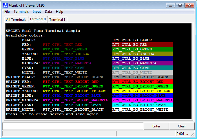
J-Link RTT Viewer
J-Link RTT Viewer is the main Windows GUI application to use all features of RTT on the debugging host.
RTT Viewer can be used stand-alone, opening an own connection to J-Link and target or in parallel to a running debug session, attaching to it and using this existing J-Link connection.
RTT Viewer supports all major features of RTT:
- Terminal output on Channel 0
- Sending text input to Channel 0
- Up to 16 virtual Terminals with only one target channel
- Controlling text output: Colored text, erasing the console
- Logging data on Channel 1
- ...
For a complete documentation of J-Link RTT Viewer refer to the J-Link User Manual (UM08001), Chapter RTT.
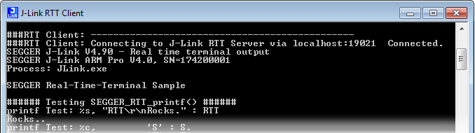
J-Link RTT Client
J-Link RTT Client acts as a Telnet client, but automatically tries to reconnect to a J-Link connection when a debug session is closed. The J-Link RTT Client as part of the J-Link Software and Documentation Pack can be used for simple RTT use cases.
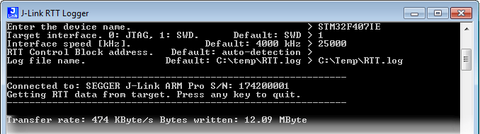
J-Link RTT Logger
With J-Link RTT Logger, data from Up-Channel 1 can be read and logged to a file. This channel can for example be used to send performance analysis data to the host. J-Link RTT Logger opens a dedicated connection to J-Link and can be used stand-alone, without running a debugger.
The source of J-Link RTT Logger can be used as a starting point to integrate RTT in other PC applications, like debuggers and is part of the J-Link SDK.
RTT performance
The performance of SEGGER RTT is significantly higher than any other technology used to output data to a host PC. An average line of text can be output in one microsecond or less. Basically only the time to do a single memcpy().

The speed comparison was done on an STM32F407 Cortex-M4 running at 168 MHz . Overhead for printf() calls removed.
Transfer speed
The maximum speed at which output data can be sent to the host depends on the target buffer size and target interface speed. Even with a small target buffer of 512 Bytes an RTT speed of up to 2 MB/s is possible with a high interface speed and 0.5 MB/s are possible with a regular J-Link model.

Target buffer size
The buffer of an RTT up channel can be relatively small. The required minimum buffer size can be approximated by the amount of data written within one millisecond, and the maximum which is written in one write action. If data is sent less frequently, the buffer should have enough space for the data which is sent with one write. If data is sent more frequently, the buffer size should suffice the maximum amount of data which is written within one millisecond. The diagram shows the required minimum buffer size when sending different amounts of data, evenly distributed, every 100 us and every 1 ms.
Required RTT buffer size:
| Transfer rate [Bytes/sec] | Buffer size at 10 kHz | Buffer size at 1 kHz |
|---|---|---|
| 10,000 | 3 | 11 |
| 20,000 | 5 | 21 |
| 50,000 | 26 | 51 |
| 100,000 | 31 | 101 |
| 200,000 | 41 | 201 |
| 500,000 | 101 | 501 |
| 1,000,000 | 301 | 1,001 |

Values are measured with J-Link Pro V7 @ 50 MHz SWD speed. Target: NXP LPC43 running at 180 MHz.
Memory footprint
The RTT implementation code uses ~500 Bytes of ROM and 24 Bytes ID + 24 Bytes per channel for the control block in RAM. Each channel requires some memory for the buffer. The recommended sizes are 1 kByte for up channels and 16 to 32 Bytes for down channels depending on the load of in- / output.
| Memory | Usage |
|---|---|
| ROM Usage | ~500 Bytes |
| RAM Usage | 24 Bytes fixed + (24 + SizeofBuffer) Bytes / channel |
RTT implementation
The SEGGER RTT implementation is written in ANSI C and can be integrated into any embedded application using the code, available for download below.
RTT can be used via a simple and easy to use API. It is even possible to override the standard printf() functions to use RTT. Using RTT reduces the time taken for printf() to a minimum and allows printing debug information to the host PC, while the application is performing time critical, real time tasks.
The SEGGER RTT implementation includes a simple implementation of printf() which can be used to write a formatted string via RTT. SEGGER_RTT_Printf() is smaller than most standard library printf implementations and does not require heap and only a configurable amount of stack.
The SEGGER RTT implementation is fully configurable with pre-processor defines. Reading and writing can be made task-safe with Lock() and Unlock() routines, the number of buffers, as well as the size of the terminal buffers can be set up easily.
API functions
| Function Name | Description |
|---|---|
| SEGGER_RTT_Read() | Read data from an input buffer. |
| SEGGER_RTT_Write() | Write data to an output buffer. |
| SEGGER_RTT_WriteString() | Write a zero-terminated string to an output buffer. |
| SEGGER_RTT_printf() | Write a formatted string to an output buffer. |
| SEGGER_RTT_GetKey() | Get one character from input buffer 0. |
| SEGGER_RTT_HasKey() | Check if a character is available in input buffer 0. |
| SEGGER_RTT_WaitKey() | Wait for a character to be available in input buffer 0 and get it. |
| SEGGER_RTT_ConfigUpBuffer() | Configure an up (output) buffer. |
| SEGGER_RTT_ConfigDownBuffer() | Configure a down (input) buffer. |
| SEGGER_RTT_Init() | Initialize RTT Control Block structure when using RAM only targets. |
| SEGGER_RTT_SetTerminal() | Set the "virtual" Terminal to use for output on channel 0 via Write and WriteString. |
| SEGGER_RTT_TerminalOut() | Send a zero-terminated string via a "virtual" terminal. |
Example code
RTT is kept as simple as possible and can be used without any configuration.
/*********************************************************************
*               SEGGER MICROCONTROLLER GmbH & Co KG                  *
*       Solutions for real time microcontroller applications         *
**********************************************************************
*                                                                    *
*       (c) 2014  SEGGER Microcontroller GmbH & Co KG                *
*                                                                    *
*       www.segger.com     Support: support@segger.com               *
*                                                                    *
**********************************************************************

----------------------------------------------------------------------
File    : RTT.c
Purpose : Simple implementation for output via RTT.
          It can be used with any IDE.
--------  END-OF-HEADER  ---------------------------------------------
*/

#include "SEGGER_RTT.h"

static void _Delay(int period) {
  int i = 100000*period;
  do { ; } while (i--);
}

int main(void) {
  do {
    SEGGER_RTT_WriteString(0, "Hello World from SEGGER!\r\n");
    _Delay(100);
  } while (1);
  return 0;
}

/*************************** End of file ****************************/
printf() with RTT
The low-level functions used in libraries for printf() can often be easily overridden, to provide own output functions. The SEGGER RTT implementation pack includes the required code for GCC/Newlib, IAR and KEIL MDK which can simply be included in the project to retarget printf() to output the data via RTT. Additionally the SEGGER RTT implementation pack includes a simplified version of printf(), SEGGER_RTT_printf(), which can be used to print formatted strings via RTT, directly, without a standard library.
System requirements
| Supported OS | |
|---|---|
| Windows | Microsoft Windows (x86/x64) |
| macOS | macOS (x86/Apple Silicon) |
| Linux | Linux (x86/x64/Arm) |
Supported targets
RTT can be used with any target, which is supported by J-Link and allows background memory access while the target is running.
| Core | RTT |
|---|---|
| Cortex-M | |
| Cortex-R | |
| Cortex-A | |
| RISC-V | |
| Renesas RX |
For some cores, RTT support is optional and certain requirements must be met. For more information please visit: https://kb.segger.com/RTT.
FAQ
Q: How does J-Link find the RTT buffer?
A: There are 2 ways: If the Debugger (IDE) knows the address of the SEGGER_RTT structure, it passes it to J-Link. This is for example done by Ozone, the J-Link Debugger or SEGGER Embedded Studio. If a debugger is used that is not SEGGER-RTT aware, such as IAR's Embedded Workbench or emIDE, then J-Link searches for the ID in the known target RAM during execution of the program, transparently in the background. The process of locating the ID string takes just fractions of a second and does not delay program execution.
Q: I am debugging a RAM-only application. J-Link finds an RTT buffer, but I get no output. What can I do?
A: In case the init section of an application is stored in RAM, J-Link might falsely identify the block in the init section instead of the actual one in the data section. To prevent this, set the define SEGGER_RTT_IN_RAM to 1. Now J-Link will find the correct RTT buffer, but only after calling the first SEGGER_RTT function in the application. A call to SEGGER_RTT_Init() at the beginning of the application is recommended.
Q: Can this also be used on targets that do not have the SWO pin?
A: Yes, the debug interface is used. This can be JTAG or SWD (2pins only!) on most Cortex-M devices, or even the FINE interface on some Renesas devices, just like the Infineon SPD interface (single pin!)
Q: Can this also be used on Cortex-M0 and M0+?
A: Yes.
Q: Some terminal output (printf) Solutions "crash" program execution when executed outside of the debug environment, because they use a Software breakpoint that triggers a hardfault without debugger or halt because SWO is not initialized. That makes it impossible to run a Debug-build in stand-alone mode. What about SEGGER-RTT?
A: SEGGER-RTT uses non-blocking mode per default, which means it does not halt program execution if no debugger is present and J-Link is not even connected. The application program will continue to work.
Q: I do not see any output, although the use of RTT in my application is correct. What can I do?
A: In some cases J-Link cannot locate the RTT buffer in the known RAM region.
In this case the possible region or the exact address can be set manually via a J-Link exec command:
- Set ranges to be searched for RTT buffer: SetRTTSearchRanges <RangeStart [Hex]> <RangeSize >[, <Range1Start [Hex]> <Range1Size>, ...] (e.g. "SetRTTSearchRanges 0x10000000 0x1000, 0x2000000 0x1000")
- Set address of the RTT buffer: SetRTTAddr <RTTBufferAddress [Hex]> (e.g. "SetRTTAddr 0x20000000")
- Set address of the RTT buffer via J-Link Control Panel -> RTT
J-Link exec commands can be executed in most applications, for example in J-Link Commander via "exec <Command>", in J-Link GDB Server via "monitor exec <Command>" or in IAR EW via "__jlinkExecCommand("<Command>");" from a macro file.
Q: Is it possible to call SetRTTAddr with the dynamic value of the RTT buffer?
A: Yes. For most debuggers/IDEs this can be done. With GDB the command can be created and executed with eval. The GDB command will be:
eval "monitor exec SetRTTAddr %p", &_SEGGER_RTTIn IAR the command can be created in a macro file funciton like this:
Set_RTT_Address () {
  __var addr;
  __var str;
  addr = &_SEGGER_RTT;
  str = __smessage "SetRTTAddr ",addr:%x;
  __jlinkExecCommand(str);
}