• Products
  • Software evaluation
  • Downloads
  • Free utilities
  • Purchase
  • Silicon Vendors
  • Support
  • About us
  • Blog
  • Forum
  • Search
  • Jobs
  • Newsletter
  • Blog
  • Contact
  • Shop
  • Program embedded systems
  • J-Link Mictor 38 Adapter

    J-Link Mictor 38 Adapter

    Seamless connectivity for Flasher

    • ARM standard mapping
    • Flexible target connection connects directly or via trace cable

    Buy now Compare Flasher adapters Documentation
    1. 1.Overview
    2. 2.Pinout & schematics
    3. 3.Suitable products
      1. 3.1.Flasher
      2. 3.2.J-Link

    Overview

    J-Link Adapter Mictor 38

    The J-Link Mictor 38 Adapter connects to the 38 pin Mictor connector. The pin out follows the single target connector pinout specification as defined in the ARM "ETM Architecture Specification". The adapter connects the GND and JTAG pins to their counterparts on the 20-pin J-Link. Trace pins present on the Mictor connector are not connected as they are not present on the 20-pin J-Link connector. The 38-pin Mictor side of the adapter can be plugged either directly into the target side or via trace cable. The J-Link side connects to J-Link via 20-pin flat cable. If you need trace capability, take a look at the J-Trace Cortex-M PRO Trace Probe.


    Pinout & schematics
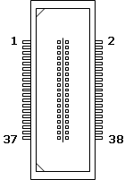
    J-Link_Mictor38_Adapter_Pinout
    Schematic diagram showing connections between a probe/programmer and a target device. The labeled signals include VTREF, TRST, TDI, TMS, TCK, RTCK, TDO, and RESET, illustrating the communication interface between the two components.
    Pin
    Signal
    5
    GND
    9
    nRES
    11
    TDO
    12,14
    VTref
    13
    RTCK
    15
    TCK
    17
    TMS
    19
    TDI
    21
    TRST

    Suitable products

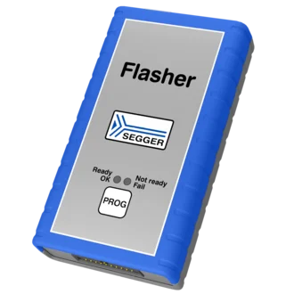
    Flasher

    A handheld device labeled "Flasher" from SEGGER, primarily gray with blue rubber edges. It features three status indicators: "Ready" (OK), "Not ready," and "Fail," along with a "PROG" button. This device is used for programming and debugging electronics.
    • Flasher Pro
    • Flasher Pro XL
    • Flasher Compact
    • Flasher ARM
    • Flasher Portable PLUS
    • Flasher Secure

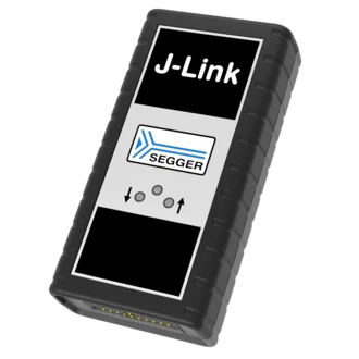
    J-Link

    Image of a J-Link debugging device from SEGGER. The device has a rectangular shape with a black casing and a silver panel featuring the "J-Link" logo and SEGGER branding. It includes several buttons and indicators for user interaction.
    • J-Link Pro PoE
    • J-Link Pro
    • J-Link Ultra
    • J-Link WiFi
    • J-Link PLUS Classic
    • J-Link PLUS Compact
    • J-Link BASE Classic
    • J-Link BASE Compact

    Get in touch with us

    Have questions or need assistance? Our Embedded Experts are here to help!

    Reach out to us for:

    • Licensing quotes
    • Technical inquiries
    • Project support


    Contact us

    • Online documentation
    • List of downloads
    • Pricing
    • Buy now
    • Regulatory documents

    Headquarters

    SEGGER Microcontroller GmbH

    Ecolab-Allee 5
    40789 Monheim am Rhein, Germany
    info@segger.com
    Tel.: +49-2173-99312-0
    Fax: +49-2173-99312-28

    Locations

    USA: SEGGER Microcontroller Systems LLC

    Boston area
    101 Suffolk Lane
    Gardner, MA 01440, USA
    us-east@segger.com
    Tel.: +1-978-874-0299
    Fax: +1-978-874-0599

    Silicon Valley
    Milpitas, CA 95035, USA
    us-west@segger.com
    Tel.: +1-408-767-4068

    China: SEGGER Microcontroller China Co., Ltd.

    Room 218, Block A, Dahongqiaoguoji
    No. 133 Xiulian Road
    Minhang District, Shanghai 201199, China
    china@segger.com
    Tel.: +86-133-619-907-60

    ISO 9001
    ISO 27001
    First-class embedded software tools since 1992
    Designed and made in Germany
    • Imprint
    • Disclaimer
    • Code of Conduct
    • Privacy Policy
    © 2026 SEGGER - All rights reserved.