• Products
  • Software evaluation
  • Downloads
  • Free utilities
  • Purchase
  • Silicon Vendors
  • Support
  • About us
  • Blog
  • Forum
  • Search
  • Jobs
  • Newsletter
  • Blog
  • Contact
  • Shop
  • Program embedded systems
  • 6-Pin Needle Adapter

    6-Pin Needle Adapter

    Seamless connectivity for Flasher

    • 6-pin needle connection
    • Compact target access
    Buy now Compare Flasher adapters Documentation
    1. 1.Overview
    2. 2.Key features
    3. 3.Pinout & schematics
    4. 4.Footprint
    5. 5.Suitable products
      1. 5.1.Flasher
      2. 5.2.J-Link

    Overview

    6-Pin Needle Adapter

    The 6-Pin Needle Adapter has been designed to connect J-Link or Flasher to a PCB which does not come with a mating connector or programming header. The designed pattern with 3 locating pins ensures that the adapter can only be connected in one way. The 6-Pin Needle Adapter allows manufacturers to save costs and space on their PCBs since there is no need to provide the PCB with additional connectors. It adapts from the standard 20-pin 0.1'' connector to a 6-pin needle connector.


    Key features

    • No additional connector required on your PCB
    • Very small footprint - even smaller than the footprint of the 10-Pin Needle Adapter
    • High reliability spring pins for secure connections
    • Designed with 3 locating pins, so the adapter can not be connected the wrong way
    • Please note: If JTAG support is required, use the 10-Pin Needle Adapter instead since the 6-Pin Needle Adapter does not provide enough pins for JTAG.

    Pinout & schematics
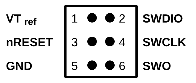
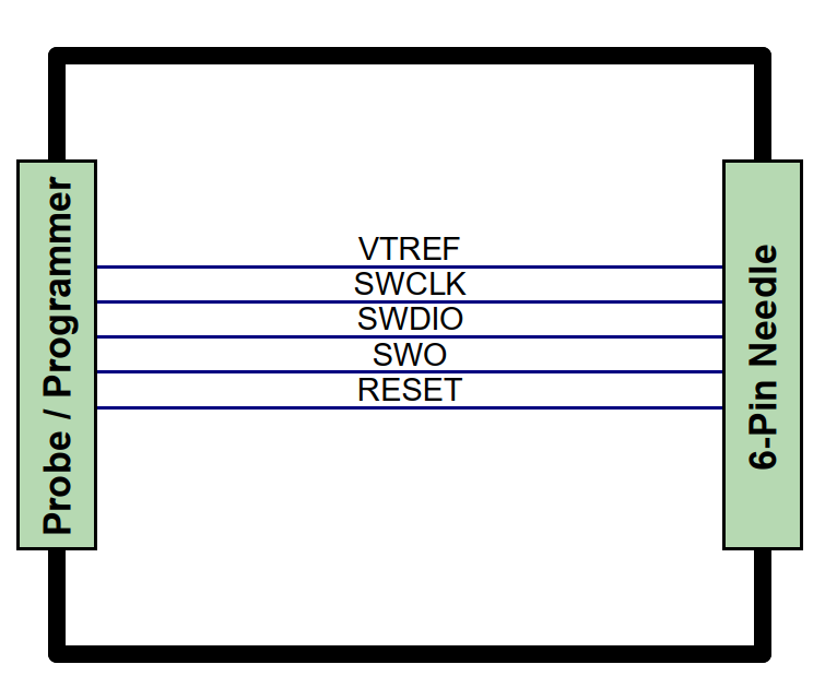
    A diagram showing a 6-pin needle connection with labeled pins: VTREF, SWCLK, SWDIO, SWO, and RESET. On the left, it is labeled "Probe / Programmer." The connection setup is represented within a rectangular outline.

    The adapter features three locating pins for precise positioning and two support legs on each side of the connector for a stable and secure connection between the pins and the PCB.
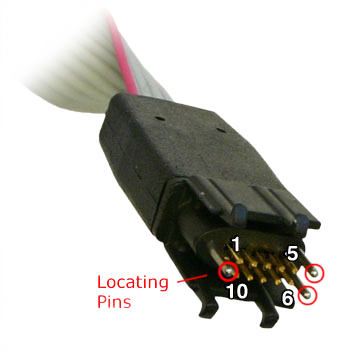

    J-Link_Needle_Adapter_Connector_pins
    Three locating pins ensure that the adapter cannot be connected the wrong way.
    A close-up image of a pair of wire cutters gripping an electrical connector. The connector features several metal pins, some gold-plated, visible inside. The background is plain white, emphasizing the tools and connection.
    In case of space problems, the two "legs" on each side can easily be cut off as shown in the image.

    Footprint

    To ensure reliable operation of the 6-Needle Adapter, we recommend implementing the footprint layout according to our specifications and following the PCB layout guidelines provided. This helps avoid common layout issues during the development process and ensures a stable connection to the flasher.

    The complete footprint, including all technical specifications, dimensions, and additional information about the cable, plug, and connector, can be found in the PDF datasheet.
    Download PDF


    Suitable products

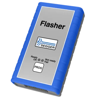
    Flasher

    A handheld device labeled "Flasher" from SEGGER, primarily gray with blue rubber edges. It features three status indicators: "Ready" (OK), "Not ready," and "Fail," along with a "PROG" button. This device is used for programming and debugging electronics.
    • Flasher Pro
    • Flasher Pro XL
    • Flasher Compact
    • Flasher Portable PLUS

    J-Link

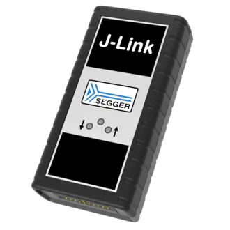
    Image of a J-Link debugging device from SEGGER. The device has a rectangular shape with a black casing and a silver panel featuring the "J-Link" logo and SEGGER branding. It includes several buttons and indicators for user interaction.
    • J-Link Pro PoE
    • J-Link Pro
    • J-Link WiFi
    • J-Link PLUS Compact
    • J-Link BASE Compact

    Get in touch with us

    Have questions or need assistance? Our Embedded Experts are here to help!

    Reach out to us for:

    • Licensing quotes
    • Technical inquiries
    • Project support


    Contact us

    • Online documentation
    • List of downloads
    • Pricing
    • Buy now
    • Regulatory documents

    Headquarters

    SEGGER Microcontroller GmbH

    Ecolab-Allee 5
    40789 Monheim am Rhein, Germany
    info@segger.com
    Tel.: +49-2173-99312-0
    Fax: +49-2173-99312-28

    Locations

    USA: SEGGER Microcontroller Systems LLC

    Boston area
    101 Suffolk Lane
    Gardner, MA 01440, USA
    us-east@segger.com
    Tel.: +1-978-874-0299
    Fax: +1-978-874-0599

    Silicon Valley
    Milpitas, CA 95035, USA
    us-west@segger.com
    Tel.: +1-408-767-4068

    China: SEGGER Microcontroller China Co., Ltd.

    Room 218, Block A, Dahongqiaoguoji
    No. 133 Xiulian Road
    Minhang District, Shanghai 201199, China
    china@segger.com
    Tel.: +86-133-619-907-60

    ISO 9001
    ISO 27001
    First-class embedded software tools since 1992
    Designed and made in Germany
    • Imprint
    • Disclaimer
    • Code of Conduct
    • Privacy Policy
    © 2026 SEGGER - All rights reserved.