• Products
  • Software evaluation
  • Downloads
  • Free utilities
  • Purchase
  • Silicon Vendors
  • Support
  • About us
  • Blog
  • Forum
  • Search
  • Jobs
  • Newsletter
  • Blog
  • Contact
  • Shop
  • Program embedded systems
  • Relay Adapter

    Relay Adapter

    Seamless connectivity for Flasher

    • Relay-based isolation
    • ATE environment protection
    Buy now Compare Flasher adapters Documentation
    1. 1.Overview
    2. 2.Technical specifications & pinout
    3. 3.Suitable products
      1. 3.1.Flasher
      2. 3.2.J-Link

    Overview

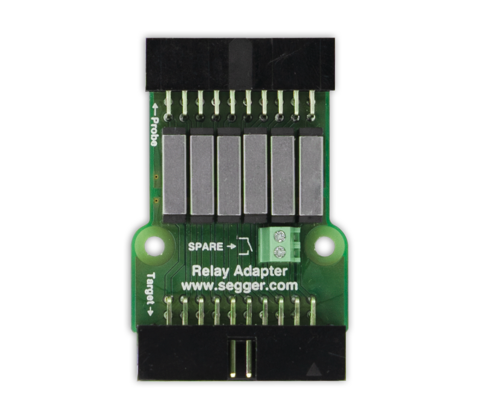
    SEGGER Relay Adapter Photo

    The Relay Adapter is used to disconnect the Flasher signals from the target by means of relay contacts. This is particularly helpful in production setups making use of automated test equipment. Such settings often require multiple test and programming devices being connected to the same lines of a nail bed. The Relay Adapter makes sure lines are switched off cleanly in order to avoid signals getting in each other's way and influencing each other. All signals including GND and VTSUPPLY will be switched and an additional switch contact will be provided for customer use. All relays will be controlled by VTSUPPLY.


    Technical specifications & pinout
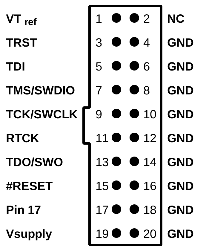
    Relay specification
    Instrumentation grade reed relays
    Contact switch current:
    1 A
    Initial contact resistance:
    < 150 mOhms
    Insulation resistance:
    > 1012 Ohms
    Current consumption:
    < 100 mA, will be taken from Flasher's target supply rail
      Download schematics


    Suitable products

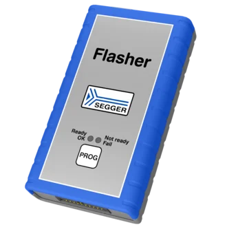
    Flasher

    A handheld device labeled "Flasher" from SEGGER, primarily gray with blue rubber edges. It features three status indicators: "Ready" (OK), "Not ready," and "Fail," along with a "PROG" button. This device is used for programming and debugging electronics.
    • Flasher Pro
    • Flasher Pro XL
    • Flasher Compact
    • Flasher ARM
    • Flasher Portable PLUS
    • Flasher Secure

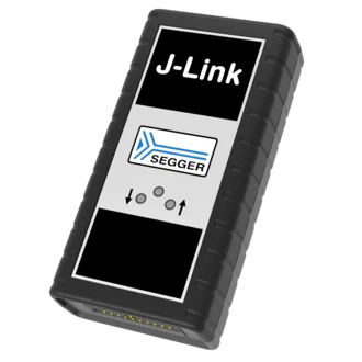
    J-Link

    Image of a J-Link debugging device from SEGGER. The device has a rectangular shape with a black casing and a silver panel featuring the "J-Link" logo and SEGGER branding. It includes several buttons and indicators for user interaction.
    • J-Link Pro PoE
    • J-Link Pro
    • J-Link Ultra
    • J-Link WiFi
    • J-Link PLUS Classic
    • J-Link PLUS Compact
    • J-Link BASE Classic
    • J-Link BASE Compact

    Get in touch with us

    Have questions or need assistance? Our Embedded Experts are here to help!

    Reach out to us for:

    • Licensing quotes
    • Technical inquiries
    • Project support


    Contact us

    • Online documentation
    • List of downloads
    • Pricing
    • Buy now

    Headquarters

    SEGGER Microcontroller GmbH

    Ecolab-Allee 5
    40789 Monheim am Rhein, Germany
    info@segger.com
    Tel.: +49-2173-99312-0
    Fax: +49-2173-99312-28

    Locations

    USA: SEGGER Microcontroller Systems LLC

    Boston area
    101 Suffolk Lane
    Gardner, MA 01440, USA
    us-east@segger.com
    Tel.: +1-978-874-0299
    Fax: +1-978-874-0599

    Silicon Valley
    Milpitas, CA 95035, USA
    us-west@segger.com
    Tel.: +1-408-767-4068

    China: SEGGER Microcontroller China Co., Ltd.

    Room 218, Block A, Dahongqiaoguoji
    No. 133 Xiulian Road
    Minhang District, Shanghai 201199, China
    china@segger.com
    Tel.: +86-133-619-907-60

    ISO 9001
    ISO 27001
    First-class embedded software tools since 1992
    Designed and made in Germany
    • Imprint
    • Disclaimer
    • Code of Conduct
    • Privacy Policy
    © 2026 SEGGER - All rights reserved.