Test Farm Power Adapter
Seamless connectivity for J-Link
- Remote power control
- Automated target reboot
Overview
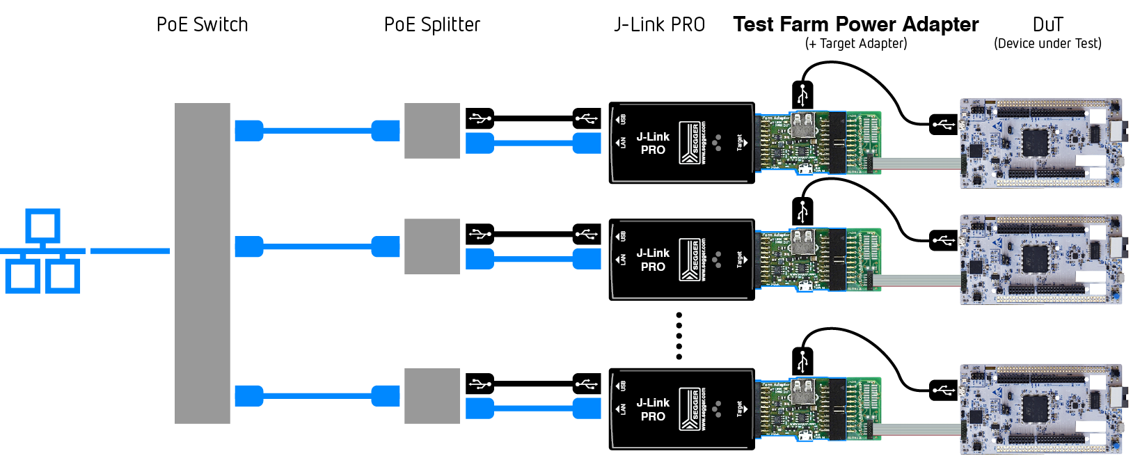
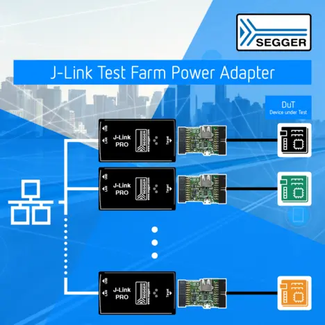
The Test Farm Power Adapter enables power that is supplied to a target through a USB connector to be switched on and off remotely using J-Link software. Since the debug signals are maintained, it can be used along with Ethernet featured debug probes like the J-Link Pro to build test farms.
What is a test farm?
In terms of embedded systems, a test farm (or “board farm” or “device farm”) consists of a number of nodes (such as evaluation boards, prototype boards, production boards, finished products, etc.) connected to a network via debug probes, making them remotely accessible to testers or developers.
It is a very efficient way to share access to hardware that is in limited supply among a number of users. Additionally, automated build systems can run tests on the same standard setup, which is ideal for regression testing, continuous integration, compiler tests, and more.
The benefits of a test farm and how to build one
Find out more about test farms, including how to build a J-Link test farm with the J-Link Test Farm Power Adapter, on our Test Farm wiki page.
Use cases
Compatibility tests
Communication reliability requires extensive test setups that generate high traffic on the communication channel. Wireless protocols such as Wi-Fi, Zigbee, and Matter are particularly prone to interference and therefore require thorough testing under challenging conditions. Test farms combine heterogeneous targets for interoperability testing with multiple identical devices to verify communication reliability at scale.
Compatibility tests
Testing firmware compatibility across different platforms or compiler changes requires a diverse range of target devices. A test farm accelerates testing by running tests in parallel across multiple targets, ensuring that firmware and compiler updates are thoroughly validated across all supported devices.
Hardware specifications
Pins and connection
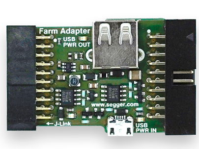
The Test Farm Power Adapter has a standard 20-pin 0.1" socket towards the J-Link and a standard 20-pin 0.1" header on the target side. It can directly be inserted between the J-Link and the debug cable maintaining a 1:1 connection of all debug signals except pin 19 which carries the target supply.
The adapter also has 2 USB connectors.
Power source and delivery
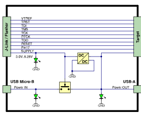
Power is delivered to the target through a USB-A host connector (USB2.0, power-only). The power source can be either the J-Link debug probe or an USB power source like a hub or wall adapter. In the first case the output voltage coming from J-Link is boosted to 5 V and is limited to around 250 mA. If the Micro USB connector of the Test Farm Power Adapter is used together with an external supply currents of 1 A and more are possible.
Package content
Related news
Suitable products
J-Link
Get in touch with us
Have questions or need assistance? Our Embedded Experts are here to help!
Reach out to us for:
- Licensing quotes
- Technical inquiries
- Project support