Port multiplication
emNet tail tagging
Extend virtually any single port CPU to n manageable interfaces at low cost. Use the fast MII/RMII interface of your CPU and internal Ethernet controller instead of slower interfaces like SPI with external Ethernet controllers.
Overview
emNet Tail Tagging is an optional extension to support Tail Tag Mode used by Micrel/Microchip Ethernet Switch Devices. These kind of switches enable system designs that typically require multiple Ethernet MAC ports to use a standard microcontroller with only one Ethernet MAC port.
The Ethernet port is connected to the switch which routes packets to the MCU and also adds an indication to the payload identifying which port received the packet. emNet Tail tagging extension will handle this identifier.
Key features
- Link status of each port can be monitored individually
- Keep your existing design and known and preferred CPU
- Each Tail Tagging interface can have its own hardware address
- Low memory footprint
- Seamless integration with the emNet TCP/IP stack
Software Requirements
The emNet Tail Tagging implementation requires the emNet TCP/IP stack and a PHY driver for a Micrel/Microchip Switch PHY that supports the Tail Tagging feature.
Hardware Requirements
A Micrel/Microchip Switch PHY supporting Tail Tagging needs to be present on your hardware.
The big advantage of using Tail Tagging instead of other methods like adding external Ethernet controllers is its simplicity that comes without any known downsides.
Easily Add Physical Ethernet Ports to Single Port MCUs
SEGGER’s TCP/IP stack offers support for the Tail Tagging feature of Micrel/Microchip Ethernet switches. SEGGER’s emNet is the first embedded IP stack to support Tail Tagging.
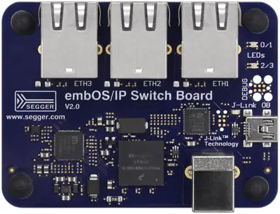
With the embOS/IP Switch Board, SEGGER is also offering hardware to evaluate the feature.
Single MAC unit CPU, Single Port Design
The typical hardware design for an Ethernet capable hardware with the MAC unit inside the CPU is shown below.
It consists of a CPU with a single internal MAC unit connected to an external single port PHY that can interface one port to the network.
The Ethernet data is transferred between MAC and PHY while the MDIO interface (typically also accessed via registers of the MAC) is used to access the PHY to configure it and periodically check the link status.
Single MAC unit CPU, Switch PHY with Tail Tagging Design
For Tail Tagging only a few simple changes to the hardware are necessary.
The main difference is that configuration is no longer done via the MDIO interface
but instead by using an extra interface like SPI or SMI.
This is due to a restricted set of registers that are available via the MDIO standard.
Typically the same registers that can be accessed via MDIO can be accessed via SPI or SMI as well,
in addition to many other registers not available via MDIO.
Using a Switch PHY with Tail Tagging not only allows you to connect multiple hosts
but also to fully control each external port/connector as if it was an additional expensive
and external Ethernet controller.
Tail Tagging Backgrounds
The Tail Tagging feature available in many Micrel/Microchip Switch PHYs is a clever way to pass information between the PHY and the TCP/IP stack
about on which port of the Switch a packet has been received or to which port(s) it should be delivered when the TCP/IP stack sends data to the network.
Contents of a Tail Tagging Frame
The picture below shows the content of a frame that is received from the Switch in the host or is sent from the host to the Switch. When the Switch has the Tail Tagging feature enabled all ports of the Switch will be used in this mode. When the Switch has the Tail Tagging feature enabled all ports of the Switch will be used in this mode.
Receiving a Frame with Tail Tagging
With Tail Tagging each Ethernet frame that is received will be added with a byte between the Ethernet data received in the frame and the checksum of the Ethernet frame itself.
This step is unseen by the Ethernet controller as the frame checksum that is built by the sender above all the Ethernet data in the frame is altered by the PHY as well to represent the correct checksum of the original Ethernet data in the frame plus the byte that has been added. Due to the correct checksum the Ethernet controller does not have to be aware of Tail Tagging at all.
emNet can then extract the information from which port the data has been received from the Tail Tagging byte and can assign the packet to the correct Tail Tagging interface in the system.
The Tail Tagging byte is stripped in this process leaving only the original data that can then be transferred to upper layer protocols.
Sending a Frame with Tail Tagging
Sending works similar to receiving a frame. Before the Ethernet frame is queued with the Ethernet controller for transmitting it to the PHY, a Tail Tagging byte is appended at the end of the data to be sent (and before the frame checksum if calculated and added by the Ethernet driver itself).
This byte contains the information to which external PHY ports the packet shall be delivered and sent out to the network.
The whole process is again unseen by the Ethernet controller as it is only aware that the data to be sent is one byte more in total like if one byte more would be sent by an upper layer protocol.


