Trace Reference Boards
The Trace Reference Boards are perfect for quick and simple trace setups and can be used as reference for custom board designs.
Overview
The Trace Reference Boards are optimal for simple and portable trace demos. These boards allow testing and verification of trace setups within minutes. They can also be used as a reference for custom hardware projects as the Trace Reference Boards are optimized for best trace signal quality.
All Trace Reference Boards come with an example project that runs out-of-the-box. For easy setup the boards can be powered using a J-Trace PRO or later. A table with currently available boards can be found below.
Please send requests for additional Trace Reference Boards to support@segger.com.
Key features
- Perfect for quick and simple trace setups
- Small footprint for optimal portability
- Numerous target devices to choose from
- Can be powered through the J-Trace PRO, no additional cabling required
- 3 LEDs implemented for flexible use in trace demo applications
- All trace signals available as test points for easy measurement setups with oscilloscopes
Trace Reference Board models
| Board | Image | Target Device | Max. CPU clock speed | Max. trace bandwidth | Debug interface | Schematics |
|---|---|---|---|---|---|---|
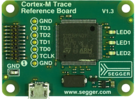
Cortex-M Trace |
| ST STM32F407 | 168 MHz | 672 Mbps with 4-bit Trace, | JTAG / SWD / SWO | |
iMX RT1050 Trace | 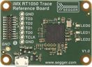 | NXP iMX RT1051/52 | 600 MHz | 1056 Mbps with 4-bit Trace, | SWD | Download |
STM32H7 Trace | 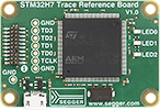 | ST STM32H743 | 400 MHz | 1064 Mbps with 4-bit Trace, 266 MHz Trace port clock* | JTAG / SWD / SWO | Download |
* Actual Trace clock is half the TPIU frequency as "half rate clocking", dual data rate is used, with sampling on both rising and falling edges.
Target connector
The following pictures show the target side pinout of the Trace Reference Board when used with SWD or JTAG respectively:
| Signal | Type | Description | |
|---|---|---|---|
| Pin 1 | VTref | Output | This is the target reference voltage. It is used by J-Link to check if the target has power, to create the logic-level reference for the input comparators and to control the output logic levels to the target. It is normally fed from Vdd of the target board and must not have a series resistor. |
| Pin 2 | SWDIO/ TMS | I/O / Input | JTAG mode set input of target CPU. This pin should be pulled up on the target. Typically connected to TMS of the target CPU. |
| Pin 4 | SWCLK/ TCK | Input | JTAG clock signal to target CPU. It is recommended that this pin is pulled to a defined state of the target board. Typically connected to TCK of the target CPU. |
| Pin 6 | SWO / TDO | Output | JTAG data output from target CPU. Typically connected to TDO of the target CPU. |
| --- | --- | --- | This pin (normally pin 7) is not existent on the 19-pin JTAG/SWD and Trace connector. |
| Pin 8 | TDI | Input | JTAG data input of target CPU.- It is recommended that this pin is pulled to a defined state on the target board. Typically connected to TDI of the target CPU. |
| Pin 9 | NC | NC | Not connected inside J-Link. Leave open on target hardware. |
| Pin 10 | nRESET | I/O | Target CPU reset signal. Typically connected to the RESET pin of the target CPU, which is typically called "nRST", "nRESET" or "RESET". |
| Pin 12 | TRACECLK | Output | Outputs trace clock. Trace clock = 1/2 CPU clock for Cortex-M devices. |
| Pin 14 | TRACEDATA[0] | Output | Output Trace data pin 0. |
| Pin 16 | TRACEDATA[1] | Output | Output Trace data pin 1. |
| Pin 18 | TRACEDATA[2] | Output | Output Trace data pin 2. |
| Pin 20 | TRACEDATA[3] | Output | Output Trace data pin 3. |
Pins 3, 5, 15, 17, 19 are GND pins connected to GND.

Preparing J-Trace PRO to supply power
J-Trace PRO is able to supply 5V power to the target side on pin 11 and pin 13. In order to do this, you may have to configure J-Trace PRO once as follows:
- Make sure that SEGGER J-Link software is installed on your machine. It can be downloaded from here: https://www.segger.com/downloads/jlink/
- Start J-Link Commander (JLink.exe), which can be found under “Start -> Programs -> SEGGER -> J-Link_Vx.xxx”
- Enter the following command: power on perm
- Connect the Trace Reference Board to J-Trace
The green LED on J-Trace PRO labeled "Target power" should light up now.
Using the Trace Reference Boards with another Arm emulator
The Trace Reference Boards have been designed for J-Trace Pro, but can also be used with other Arm emulators with the same pin-out. Do this at your own risk!