SEGGER Evaluation Software for Keil MCB1800
SEGGER Evaluation Software
SEGGER Notifications
Subscribe to SEGGER Evaluation Software Notifications
Data Sheets
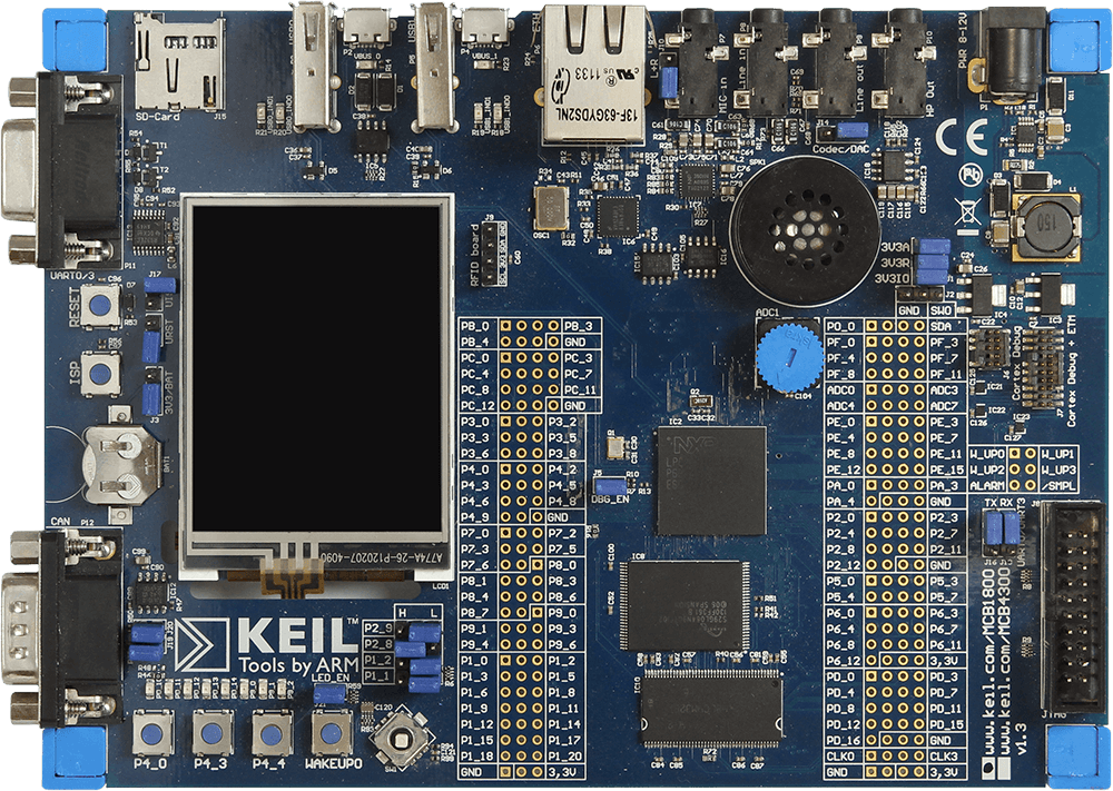
Keil MCB1800
- 180MHz ARM Cortex-M3 processor-based MCU in LBGA256
- On-Chip SRAM: 136KB (LPC1857), 200KB (LPC1850)
- On-Board Memory: 16MB NOR Flash, 4MB Quad-SPI Flash, 16 MB SDRAM, & 16KB EEPROM (I2C)
- Color QVGA TFT LCD with touchscreen
- 10/100 Ethernet Port
- High-speed USB 2.0 Host/Device/OTG interface (USB host + Micro USB Device/OTG connectors)
- Full-speed USB 2.0 Host/Device interface (USB host + micro USB Device connectors)
- CAN interfaces
- Serial/UART Port
- MicroSD Card Interface
- 4 user push-buttons + reset
- Digital Temperature Sensor (I2C)
- Analog Voltage Control for ACD Input
- Audio CODEC with Line-In/Out and Microphone/headphone connector + Speaker
- Debug Interface Connectors
- 20-pin JTAG (0.1 inch)
- 10-pin Cortex debug (0.05 inch)
- 20-pin Cortex debug + ETM Trace (0.05 inch)
LPC1857FET256
- ARM Cortex-M3 processor, running at CPU frequencies of up to 180 MHz
- ARM Cortex-M3 built-in Memory Protection Unit (MPU) supporting eight regions
- ARM Cortex-M3 built-in Nested Vectored Interrupt Controller (NVIC)
- Non-maskable Interrupt (NMI) input
- JTAG and Serial Wire Debug, serial trace, eight breakpoints, and four watch points
- Enhanced Trace Module (ETM) and Enhanced Trace Buffer (ETB) support
- System tick timer
- Up to 1 MB on-chip dual bank flash memory with flash accelerator
- 16 kB on-chip EEPROM data memory
- 136 kB SRAM for code and data use
- Multiple SRAM blocks with separate bus access
- 64 kB ROM containing boot code and on-chip software drivers
- 32-bit One-Time Programmable (OTP) memory for general-purpose use
- Crystal oscillator with an operating range of 1 MHz to 25 MHz
- 12 MHz internal RC oscillator trimmed to 1 % accuracy over temperature and voltage
- Ultra-low power RTC crystal oscillator
- Three PLLs allow CPU operation up to the maximum CPU rate without the need for a high-frequency crystal; the second PLL is dedicated to the High-Speed USB, the third PLL can be used as audio PLL
- Clock output
- State Configurable Timer (SCT) subsystem on AHB
- Global Input Multiplexer Array (GIMA) allows to cross-connect multiple inputs and outputs to event driven peripherals like timers, SCT, and ADC0/1
- Quad SPI Flash Interface (SPIFI) with 1-, 2-, or 4-bit data at rates of up to 40 MB per second
- 10/100T Ethernet MAC with RMII and MII interfaces and DMA support for high throughput at low CPU load; support for IEEE 1588 time stamping/advanced time stamping (IEEE 1588-2008 v2)
- One High-speed USB 2.0 Host/Device/OTG interface with DMA support and on-chip high-speed PHY (USB0)
- One High-speed USB 2.0 Host/Device interface with DMA support, on-chip full-speed PHY and ULPI interface to external high-speed PHY (USB1)
- USB interface electrical test software included in ROM USB stack
- Four 550 UARTs with DMA support: one UART with full modem interface; one UART with IrDA interface; three USARTs support UART synchronous mode and a smart card interface conforming to ISO7816 specification
- Two C_CAN 2.0B controllers with one channel each
- Two SSP controllers with FIFO and multi-protocol support; both SSPs with DMA support
- One Fast-mode Plus I2C-bus interface with monitor mode and with open-drain I/O pins conforming to the full I2C-bus specification; supports data rates of up to 1 Mbit/s
- One standard I2C-bus interface with monitor mode and standard I/O pins
- Two I2S interfaces with DMA support, each with one input and one output
- External Memory Controller (EMC) supporting external SRAM, ROM, NOR flash, and SDRAM devices
- LCD controller with DMA support and a programmable display resolution of up to 1024H x 768V; supports monochrome and color STN panels and TFT color panels; supports 1/2/4/8 bpp Color Look-Up Table (CLUT) and 16/24-bit direct pixel mapping
- SD/MMC card interface
- Eight-channel General-Purpose DMA (GPDMA) controller can access all memories on the AHB and all DMA-capable AHB slaves
- Up to 164 General-Purpose Input/Output (GPIO) pins with configurable pull-up/pull-down resistors and open-drain modes
- GPIO registers are located on the AHB for fast access; GPIO ports have DMA support
- Up to 8 GPIO pins can be selected from all GPIO pins as edge and level sensitive interrupt sources
- Two GPIO group interrupt modules enable an interrupt based on a programmable pattern of input states of a group of GPIO pins
- Four general-purpose timer/counters with capture and match capabilities
- One motor control PWM for three-phase motor control
- One Quadrature Encoder Interface (QEI)
- Repetitive Interrupt timer (RI timer)
- Windowed watchdog timer
- Ultra-low power Real-Time Clock (RTC) on separate power domain with 256 bytes of battery powered backup registers
- Event recorder with three inputs to record event identification and event time; can be battery powered
- Alarm timer; can be battery powered
- One 10-bit DAC with DMA support and a data conversion rate of 400 kSamples/s
- Two 10-bit ADCs with DMA support and a data conversion rate of 400 kSamples/s
- Hardware-based AES decryption programmable through an on-chip API
- Two 128-bit secure OTP memories for AES key storage and customer use
- Random Number Generator (RNG) accessible through AES API
- Unique ID for each device
- Single 3.3 V (2.2 V to 3.6 V) power supply with on-chip internal voltage regulator for the core supply and the RTC power domain
- RTC power domain can be powered separately by a 3 V battery supply
- Four reduced power modes: Sleep, Deep-sleep, Power-down, and Deep power-down
- Processor wake-up from Sleep mode via wake-up interrupts from various peripherals
- Wake-up from Deep-sleep, Power-down, and Deep power-down modes via external interrupts and interrupts generated by battery powered blocks in the RTC power domain
- Brownout detect with four separate thresholds for interrupt and forced reset
- Power-On Reset (POR)